Cables
All connections between device components in Nautobot are represented using cables. A cable represents a direct physical connection between termination points, such as between a console port and a patch panel port, or between two or more network interfaces.
Each cable may be assigned a type, label, length, and color. Each cable must also be assigned to an operational status. The following statuses are available by default:
- Connected
- Planned
- Decommissioning
Caution
The Connected status for cables has special significance in Nautobot. A path trace (as described below) considers a given path to be reachable/traversable if and only if all cables in the path have the Connected status; if any cable has a different status, the path will be flagged as unreachable. Do not delete or rename the Connected status.
The ends of a cable are sometimes referenced as "A" and "B" for clarity, however standard point-to-point cables are direction-agnostic and the order in which terminations are made has no intrinsic meaning. (Breakout cables, see below, use "A" for the "trunk" end with fewer connectors, and "B" for the "breakout" end with more connectors.)
Cables may be terminated to the following "cable termination" objects:
- Circuit terminations
- Console ports
- Console server ports
- Interfaces
- Pass-through ports (front and rear)
- Power feeds
- Power outlets
- Power ports
Added in version 3.2.0 — Cable to Cable Termination model
The database representation of the associations between a cable and its terminations is implemented by the Cable to Cable Termination model. This intermediary model was introduced in Nautobot 3.2 to support breakout cables (see below) that may have more than two terminations. For backwards compatibility purposes, the cable model still provides some capabilities similar to the previously-present termination_a and termination_b fields, particularly in the REST API and GraphQL, but code (Apps or Jobs) that interact with cables may need to be updated to account for the changed data model.
Partially-Connected, Disconnected, and Repurposed Cables
Added in version 3.2.0
Prior to Nautobot 3.2, every cable was required to have both of its endpoints defined at all times, and a cable's terminations could not be changed once created (the cable had to be deleted and recreated instead). As of Nautobot 3.2, a cable's terminations are no longer fixed at creation, which enables several new modeling capabilities:
- A partially-connected cable may have a termination on only one of its sides (for example, a patch cable that has been plugged into a switch port but whose far end is not yet connected). For a breakout cable, any subset of its connectors may be terminated.
- A fully-disconnected cable may exist with no terminations at all, for example to pre-stage a planned cable or to retain a cable record whose endpoints have both been removed.
- A cable's terminations may be added, changed, or removed after the cable is created, without deleting and recreating the cable. This can be done through the cable edit form, the REST API
terminationsfield, or programmatically (see Cable to Cable Termination).
A cable that is missing one or both terminations is fully valid, but any path trace through it will naturally halt at the missing termination.
Breakout Cables
Added in version 3.2.0
A cable can now optionally be assigned to a defined cable type. That model is primarily used to describe breakout cable types, but can also be used to describe types of point-to-point cables as well, in cases where the basic type field on a cable is insufficiently detailed.
When a cable is associated with a breakout cable type, it becomes permissible to assign more than two cable termination objects to that cable, up to the limits defined by the cable type. For example, a 1x4 breakout cable type will naturally allow cables of that type to have a single "A" side termination and up to four "B" side terminations. These terminations will each be recorded in the database as distinct cable to cable termination records.
Note that not all cable termination types are permitted to be associated to breakout cables - specifically, only the following models are supported at this time:
- Circuit terminations
- Interfaces
- Pass-through ports (front and rear)
For more information, see the Breakout Cables feature guide
Tracing Cables
A cable may be traced from either of its endpoints by clicking the "trace" button. (A REST API endpoint also provides this functionality.) Nautobot will follow the path of connected cables from this termination across the directly connected cable to the far-end termination. If the cable connects to a pass-through port, and the peer port has another cable connected, Nautobot will continue following the cable path until it encounters a non-pass-through or unconnected termination point. The entire path will be displayed to the user.
In the example below, three individual cables comprise a path between devices A and D:
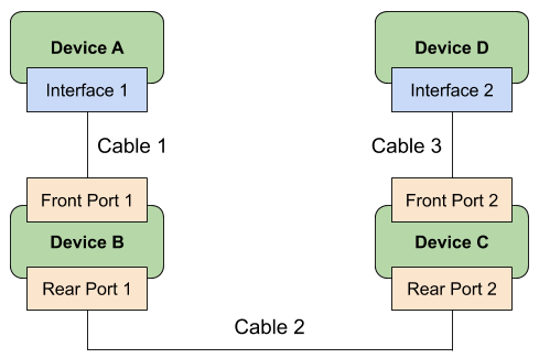
Traced from Interface 1 on Device A, Nautobot will show the following path:
- Cable 1: Interface 1 to Front Port 1
- Cable 2: Rear Port 1 to Rear Port 2
- Cable 3: Front Port 2 to Interface 2
A cable can also be traced through a circuit.
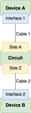
Traced from Interface 1 on Device A, Nautobot will show the following path:
- Cable 1: Interface 1 to Side A
- Cable 2: Side Z to Interface 2